Date:Sep 25, 2026
A throttle position sensor does more than report whether a throttle plate is open or closed. It converts throttle movement into an electrical signal that the ECU can interpret. The relationship between throttle position sensor position and signal voltage is therefore critical to engine control.
Many conventional TPS designs operate from a 5 V reference circuit. A typical signal may sit around 0.5 V with the throttle closed and rise toward 4.0–4.5 V at wide-open throttle. Exact values vary by vehicle, so manufacturer specifications should always take priority.
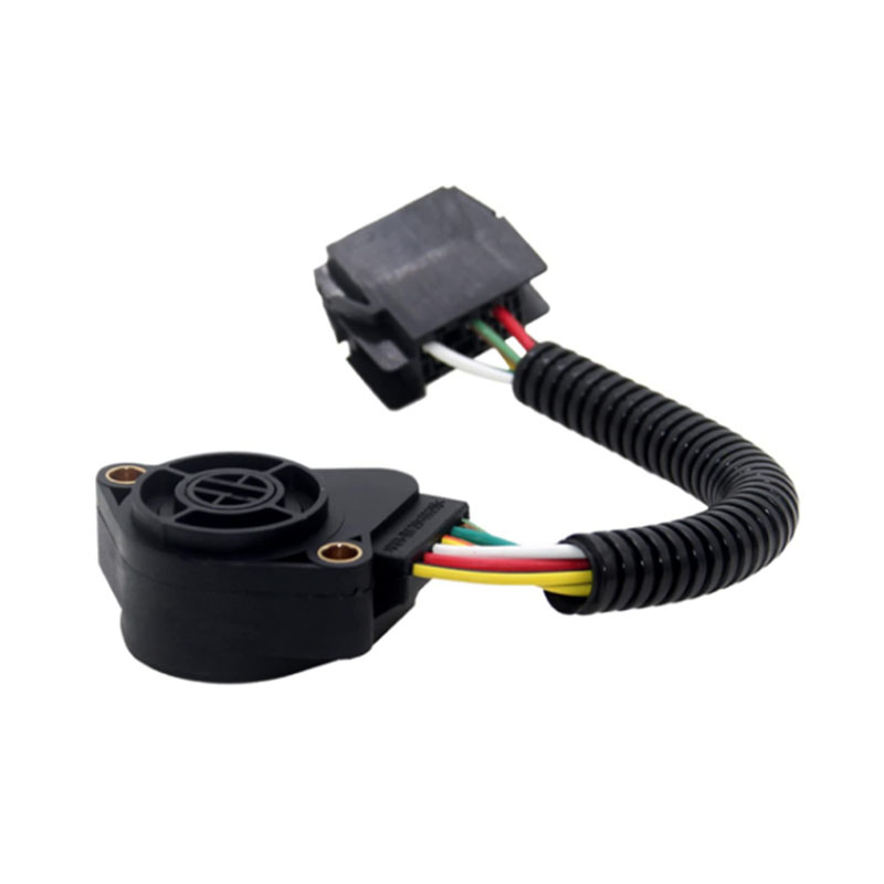
A healthy sensor should produce a continuous signal as the throttle moves through its operating range. The important factor is not simply the starting and ending voltage. The signal should also change smoothly between those points.
| Throttle Condition | Typical TPS Signal | ECU Interpretation |
| Closed throttle | About 0.4–1.0 V | Closed or near-idle position |
| Partial opening | Variable voltage | Part-throttle operation |
| Wide-open throttle | About 4.0–4.8 V | High throttle demand |
These figures are general diagnostic references rather than universal specifications. Snap-on documentation, for example, lists approximately 0.5 V at closed throttle and 4.0 V at full throttle for typical systems, while Fluke describes approximately 0.4–0.7 V and 4.0–4.8 V as common ranges.
Moving the throttle slowly from closed to fully open provides more information than checking a single voltage point. A functioning potentiometer-style TPS should generate a smooth signal without sudden drops, spikes or dead areas.
The ECU is designed to recognize that a TPS signal should remain within a plausible electrical range. A signal approaching the 5 V reference or dropping close to ground can therefore attract diagnostic attention.
For example, P0122 is commonly associated with a TPS circuit low-input condition, while P0123 represents a high-input condition. Diagnostic references describe thresholds around 0.17–0.2 V for some low-input systems and above approximately 4.8 V for high-input conditions, although the actual thresholds vary by vehicle.
An unusual TPS reading can create an interpretation problem. A signal close to 5 V while the throttle is physically closed does not necessarily represent genuine wide-open throttle. It may instead indicate a wiring fault, incorrect sensor installation, internal sensor failure or another circuit problem.
Technical service examples demonstrate why context matters. One diagnostic case documented a closed-throttle TPS signal of approximately 5.0 V, even though the expected closed-throttle value was around 0.8 V. The abnormal signal affected the controller's interpretation of throttle demand and fuel delivery.
The ECU does not necessarily evaluate TPS information in isolation. Throttle position can be compared with other engine parameters, such as MAP, MAF and RPM, to determine whether the reported operating condition makes sense.
A vehicle reporting a very high throttle position while engine speed, manifold pressure and airflow remain consistent with a closed-throttle condition presents a data correlation problem. This is why a range/performance code such as P0121 does not always mean that the TPS has completely stopped working. The signal can remain electrically present while still being implausible relative to other engine data.
| Observed TPS Behavior | Possible Area to Investigate |
| Signal outside expected range | TPS circuit, wiring or reference supply |
| Intermittent voltage drop | Sensor track or electrical connection |
| Normal voltage but incorrect throttle percentage | Calibration or ECU interpretation |
| TPS disagrees with MAP/MAF/RPM | Signal correlation or another engine-control input |
| Dual TPS signals disagree | Sensor correlation or electronic throttle system |
Modern electronic throttle systems can use multiple position signals. Instead of relying on a single potentiometer, some throttle bodies contain two position sensors so the ECU can compare their outputs for plausibility and safety monitoring. Diagnostic systems may therefore display TPS1 and TPS2 separately.
This changes the meaning of throttle position sensor position. A scan tool might display throttle position as a percentage, an angle, or an electrical voltage. These values are related, but they are not necessarily interchangeable across different vehicle platforms.
A common misunderstanding is that a closed throttle should generate zero volts. Most potentiometric TPS circuits intentionally operate above ground at closed throttle. A value around 0.5 V can represent a closed position while the reference circuit remains near 5 V.
This electrical margin also gives the ECU room to distinguish a normal closed-throttle signal from an open circuit or short condition.
A TPS can provide a plausible voltage while the actual throttle position differs from what the ECU expects. Sensor mounting, throttle-shaft movement, internal wear and calibration can all influence the relationship between physical movement and electrical output.
These three values need to remain logically aligned. A correct diagnosis therefore looks beyond a single voltage reading and considers the complete signal sweep, wiring, reference voltage, throttle movement and ECU data.
The value of throttle position sensor position data lies in its ability to show what the engine controller believes is happening at the throttle. A smooth signal provides a consistent representation of throttle movement, while spikes, dropouts, implausible values or sensor disagreement can reveal problems that may not be visible from external inspection.
For automotive parts professionals, this also highlights why TPS replacement should be based on application and electrical specifications rather than appearance alone. Connector configuration, reference voltage, signal range, sensor arrangement and throttle-body compatibility all deserve attention when evaluating a replacement component.
Related Products
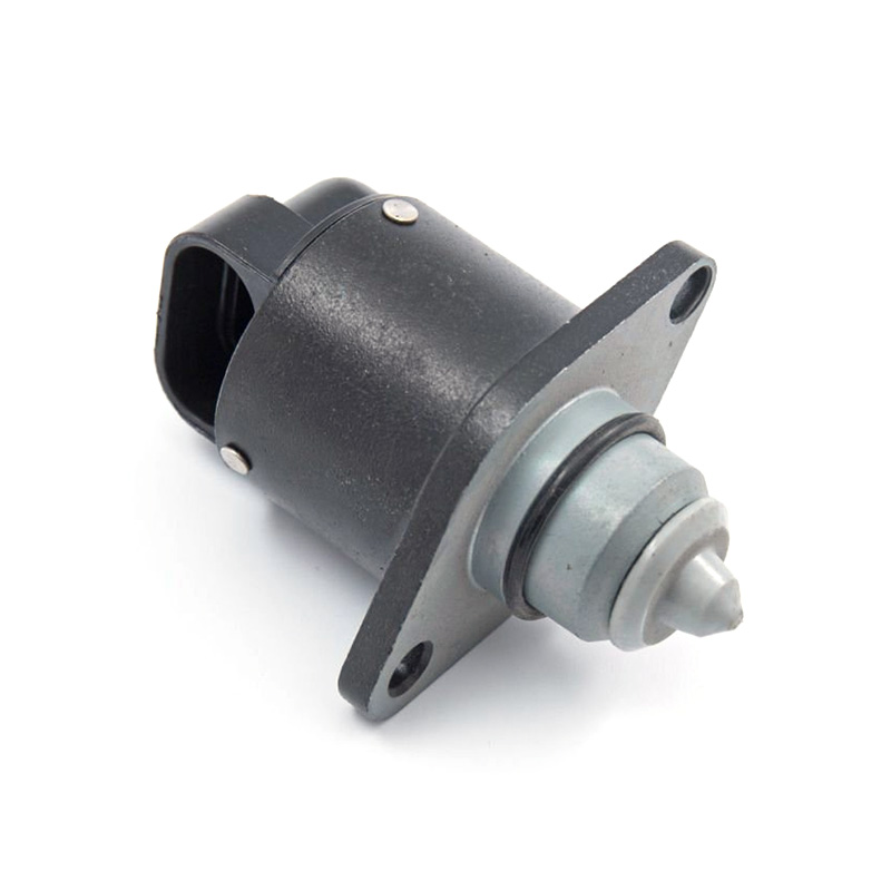
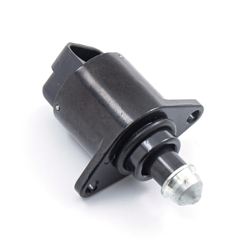
OE/Part Numbers: 1920AH A96157 B35/00
Compatible Brands: for Peugeot, Citroen
Compatible Vehicles & Years:
- for Citroen Saxo
- for Peugeot 106
- for Peugeot 206 (Schragheck /SW)
-for Peugeot 306 (Break / Schragheck)
-for Peugeot Partner (Combispace / Kasten)
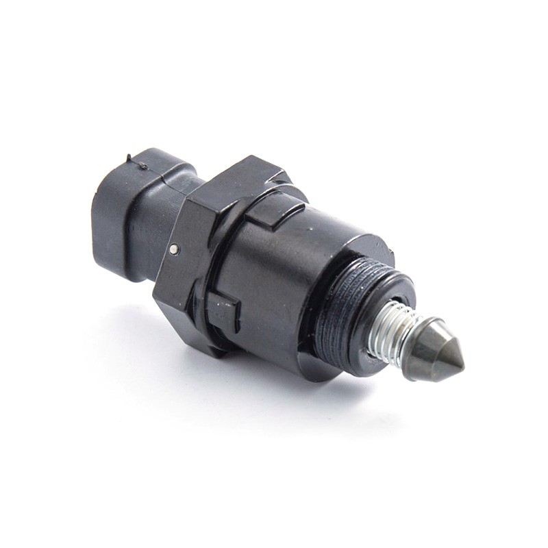
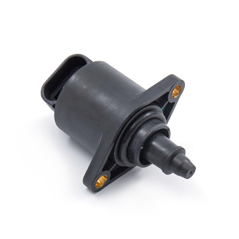
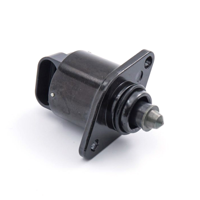
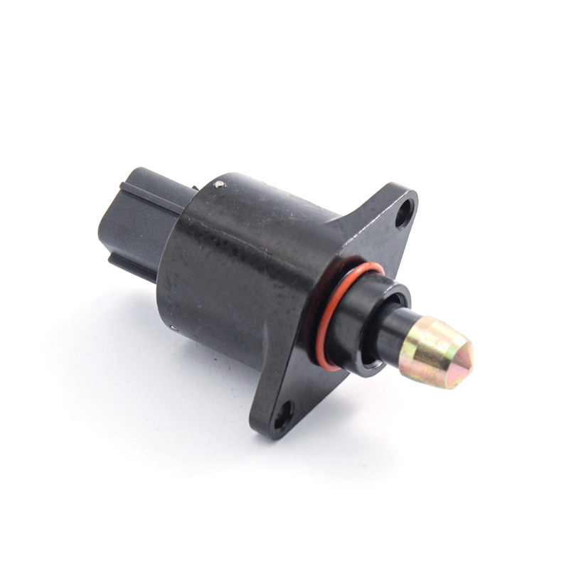
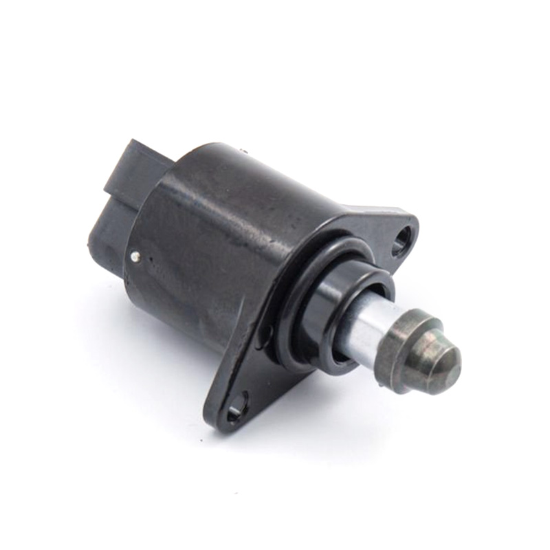
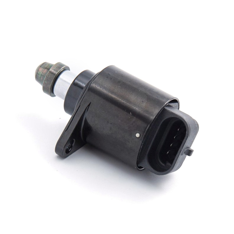
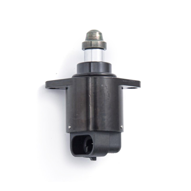
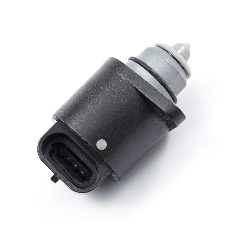
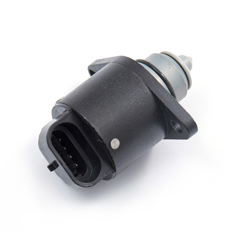
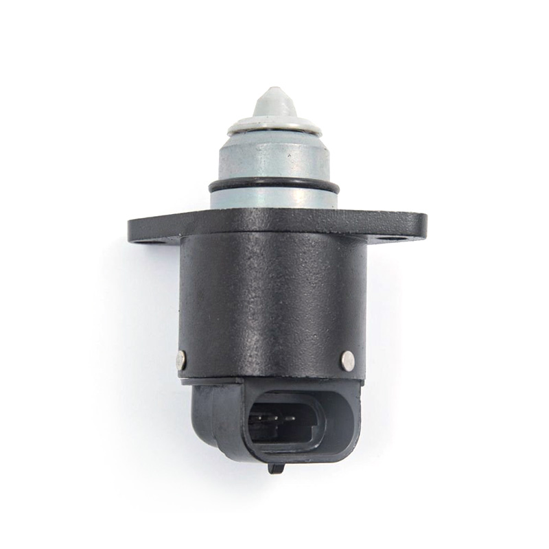
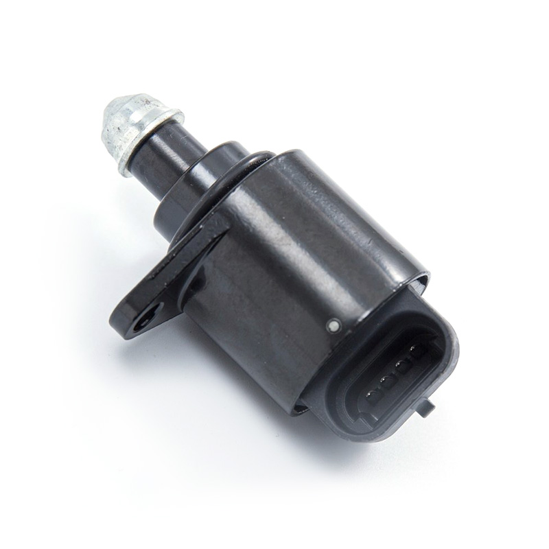
Key Functions: This idle stepper motor regulates engine idle speed, ensuring stable performance, smooth cold starts, and preventing stalling under varying loads.
Features & Advantages:
1. Direct OEM Fit & Function.
2. High-Quality Components for Reliability.
3. Rigors Quality Control.
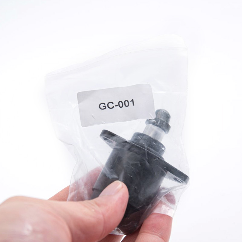
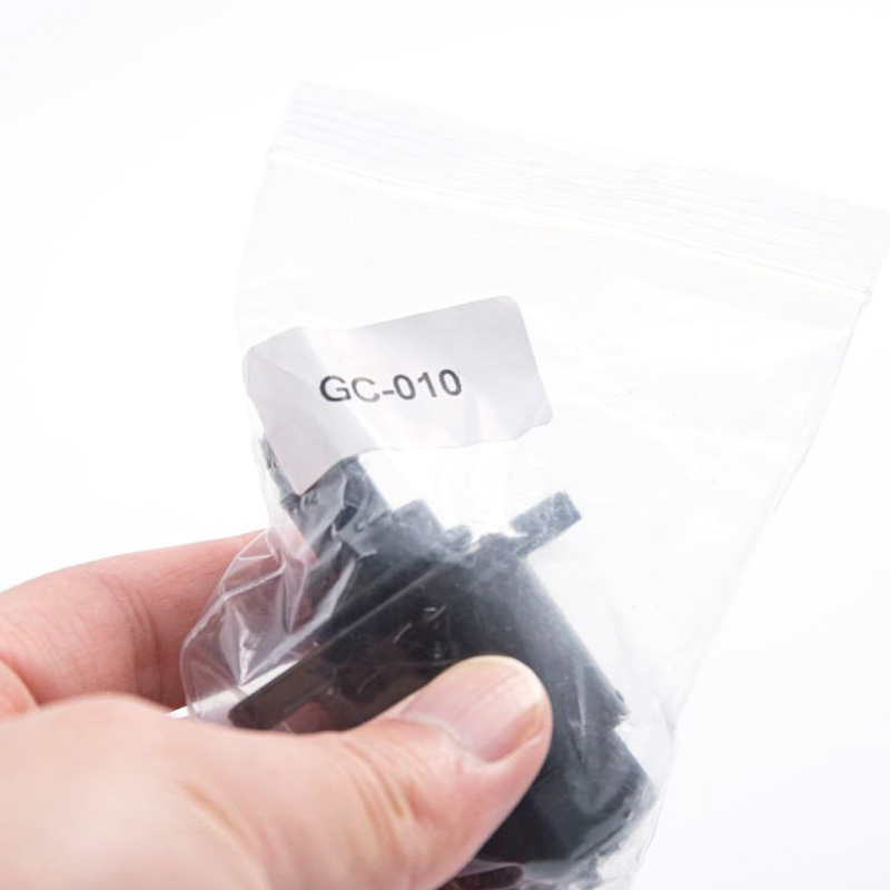
GC-010
REF OE:
SHORT CODE: D5184
APPLICATION:
FIAT PALIO/SIENA-VW GOL 1000,TEMPRA;
VALVE IACV CHEV N300
Factory direct from China for idle air control valve,first choice to buying.
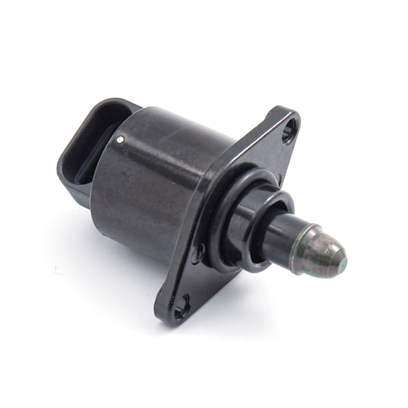
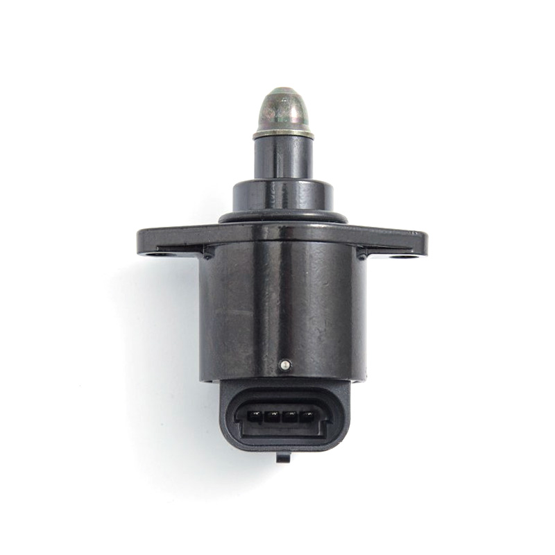
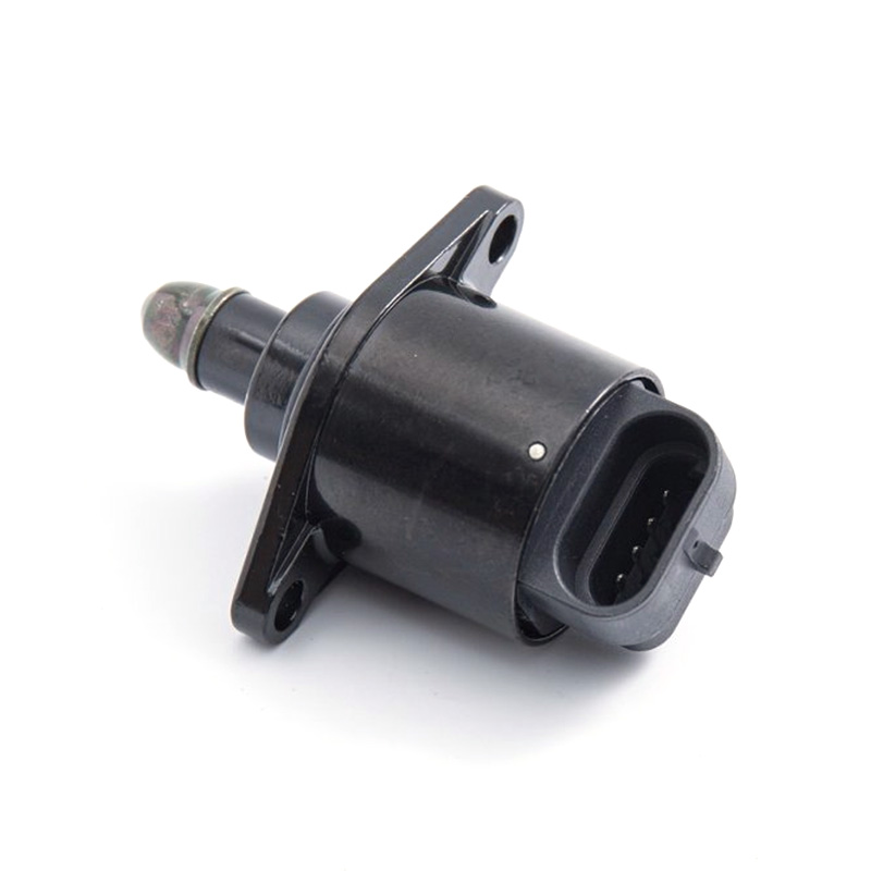
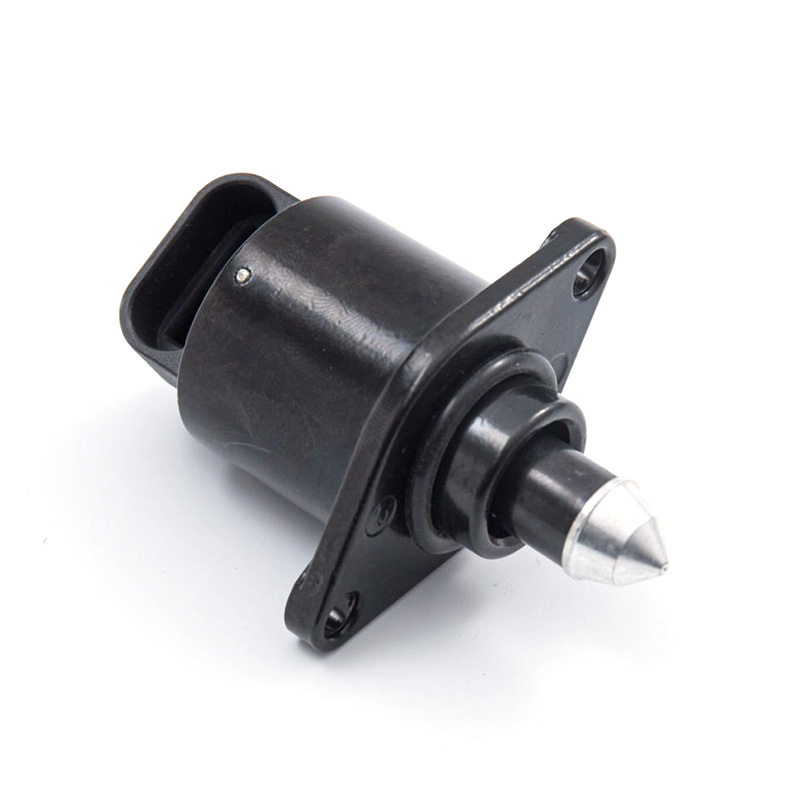
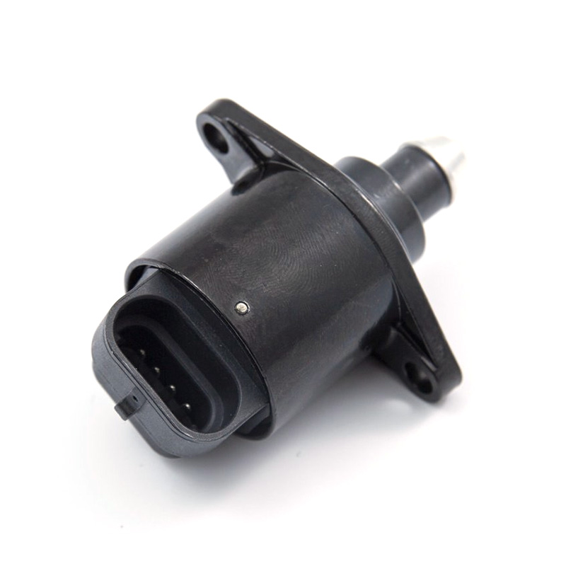
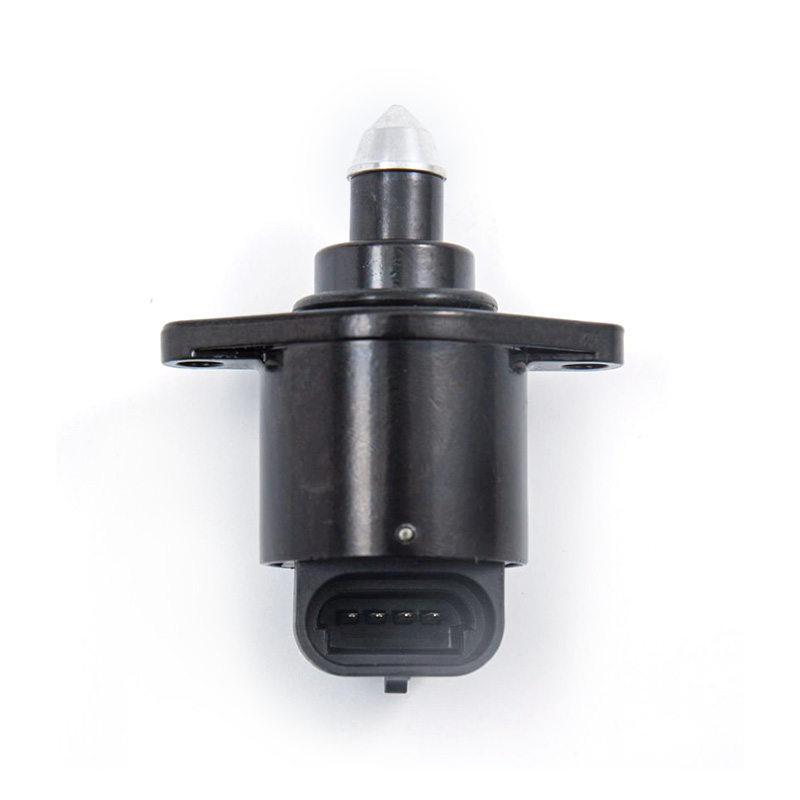
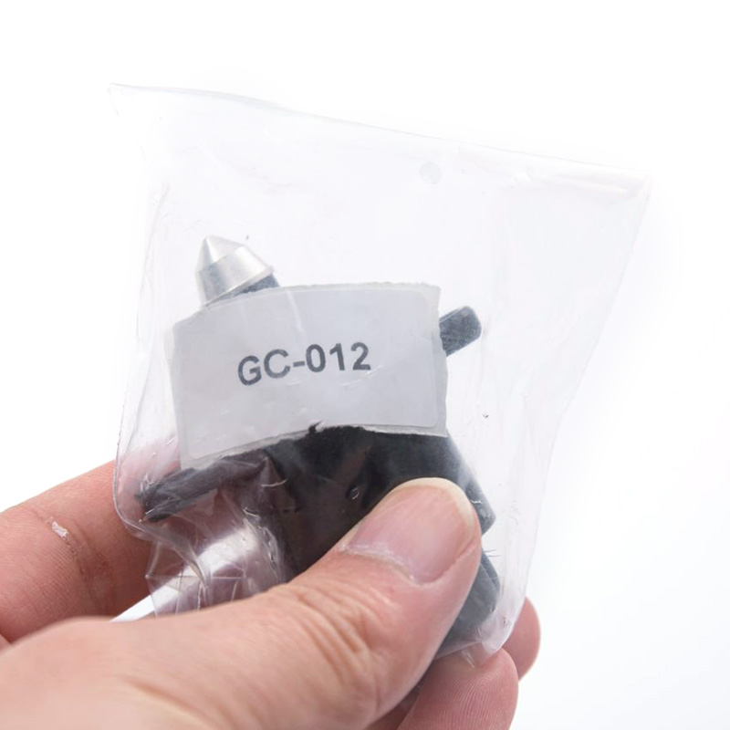
GC-012
REF OE:
HOT-STAMP:D5174
RENAULT:7701047909
APPLICATION:
RENAULT MEGANE Cabriolet/Classic/Coach/Grandtour;RENAU MEGANE I/Scenic
China auto parts wholesale,idle air control valve high quality with competitive price!
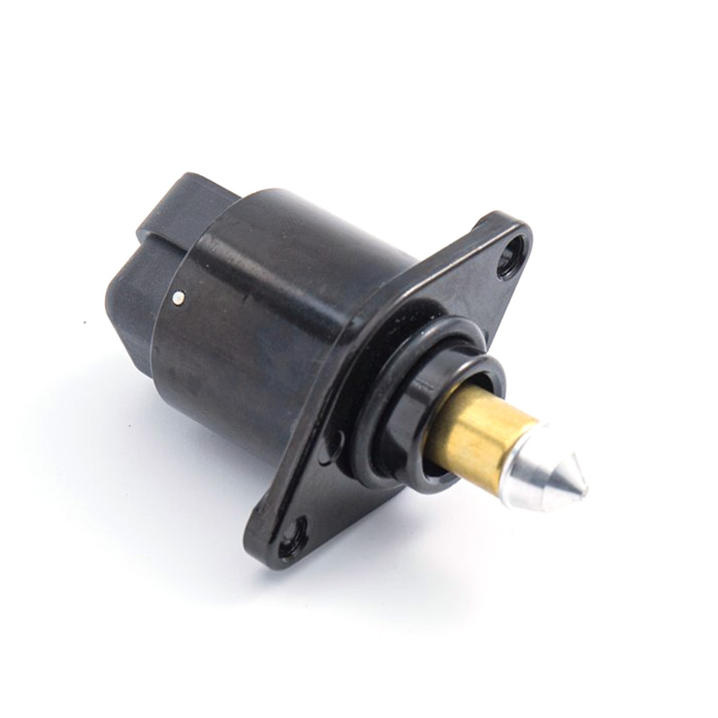
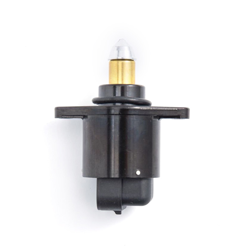
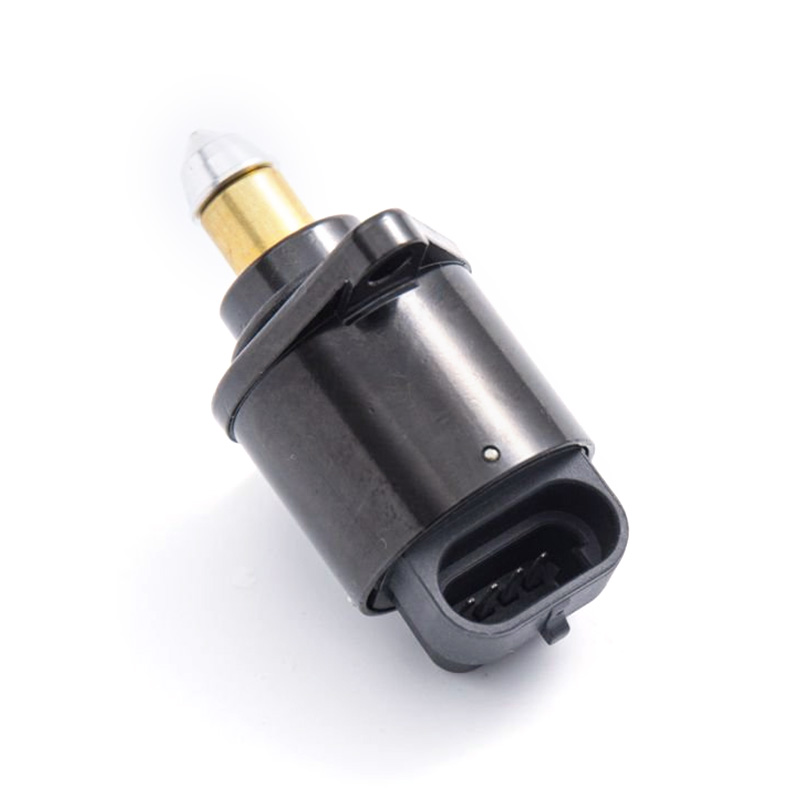
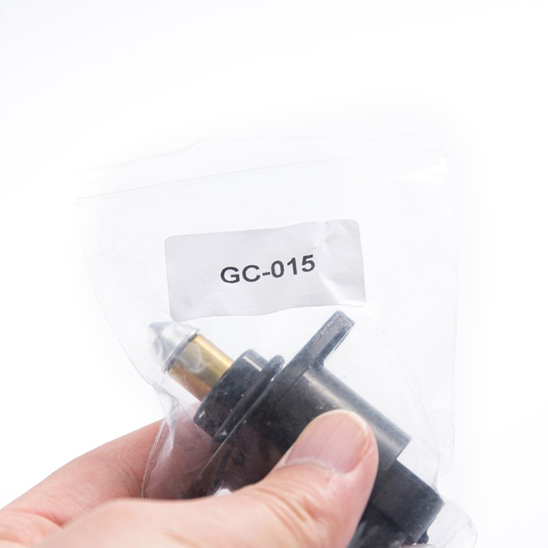
GC-015
REFERENCE OE:
SHORT CODE:D95177
RENAULT:7701206370
APPLICATION:
RENAULT 19II/19II Chamade;
RENAULT MEGANE Classic/Grandtour;
RENAU MEGANE I/Scenic;
RENAULT RAPID Kasten
Buy idle air control valve from China factory!
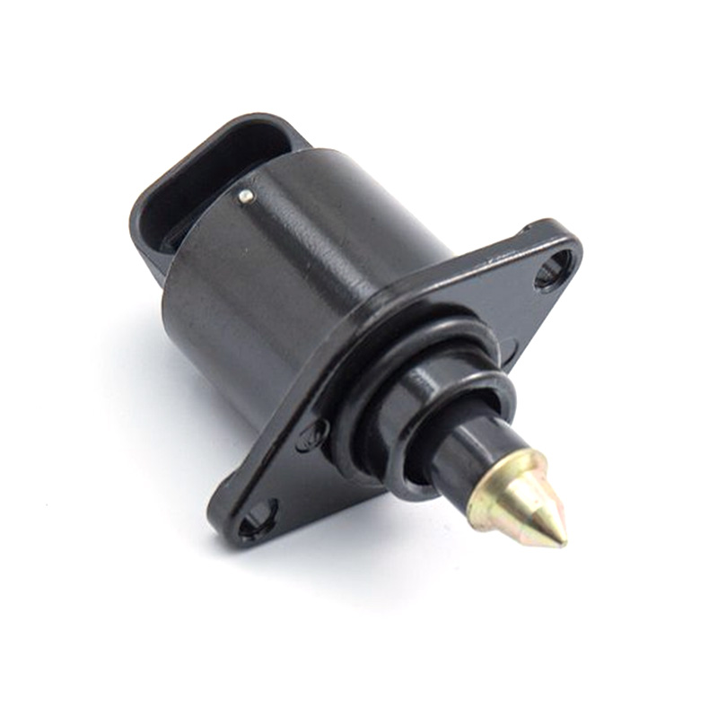
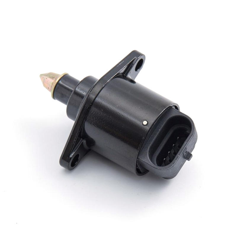
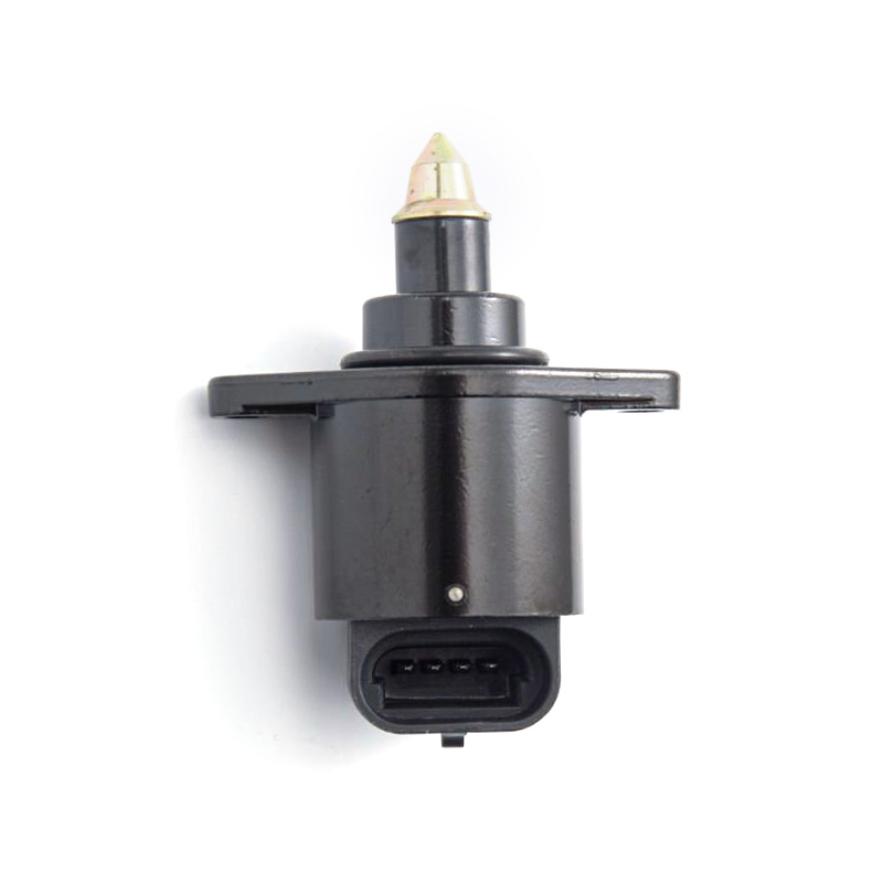
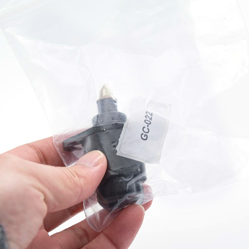
GC-022
REFERENCE OE:
SHORT CODE:B08/01
MARELLI:40380202
VDO:AT-00801R
VW:0269060491
FIAT:7076356
FORD:F5PF.9N825 .AA
APPLICATION:
VW,FIAT,FORD
Idle air control valve wholesale and retail,China manufacture direct!
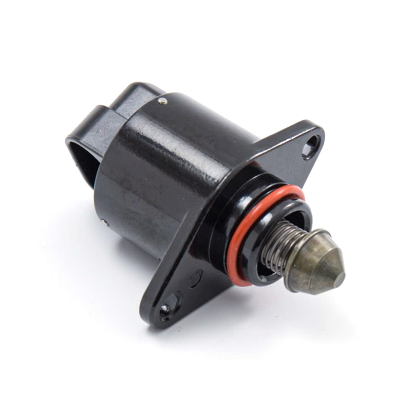
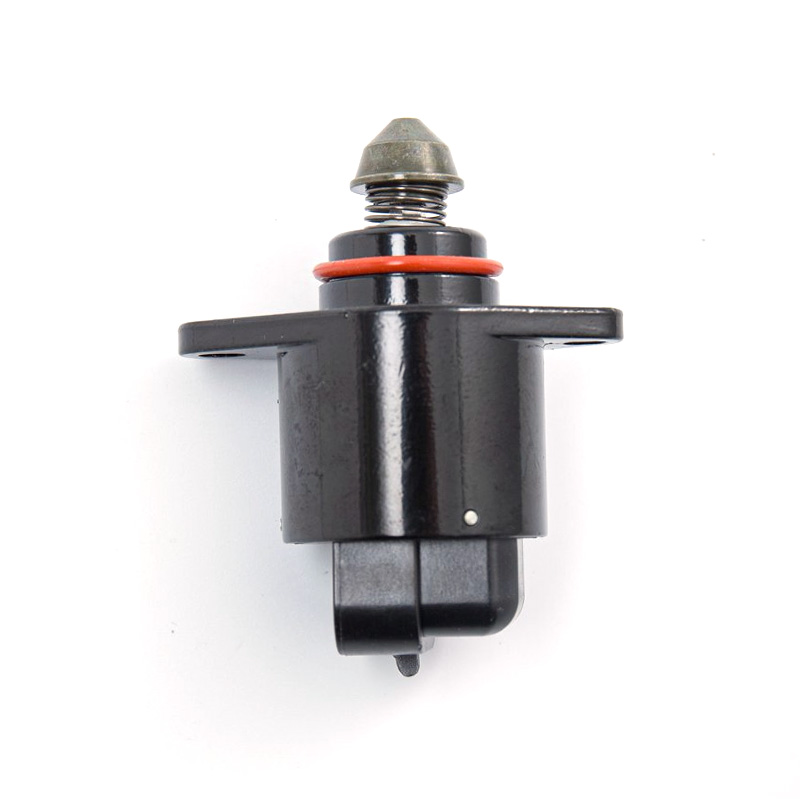
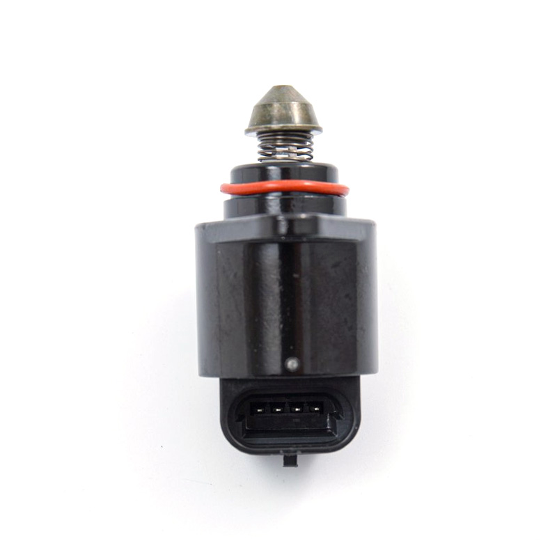
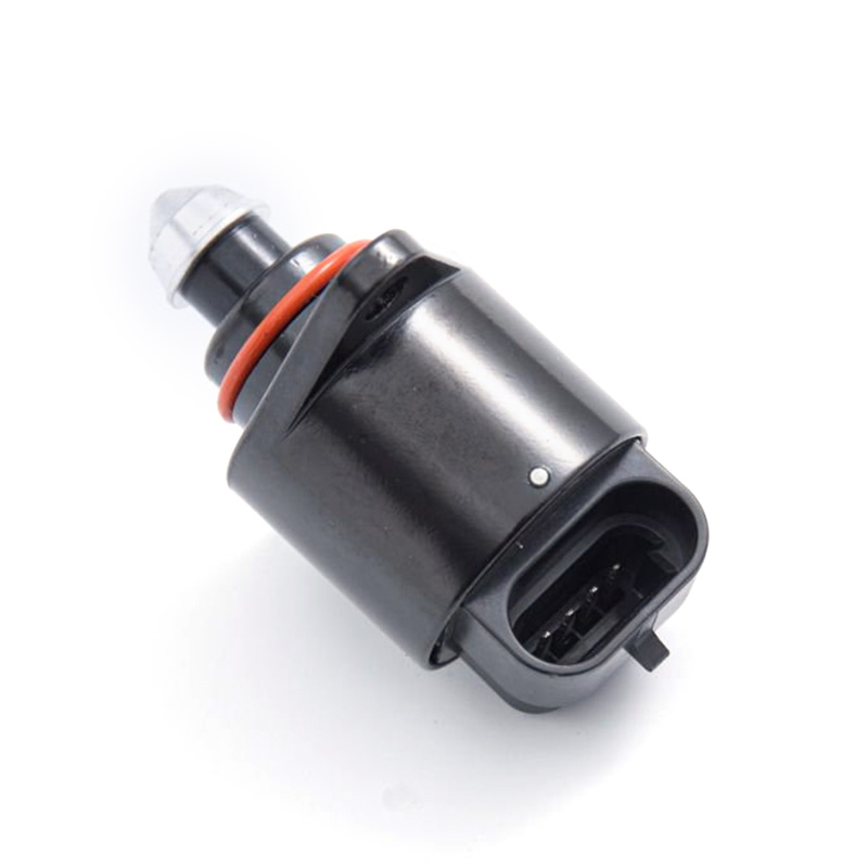
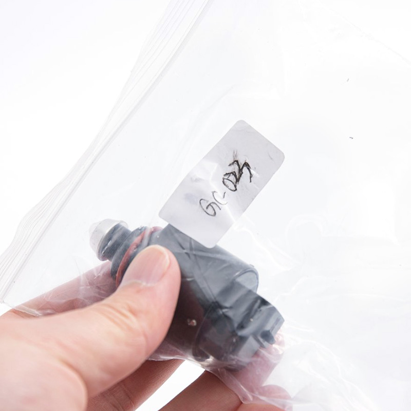
GC-023
REFERENCE OE:
GM 17112350 STD:AC5 17111808; WELLS:AC107;
APPLICATION:
Buick Century Sedan/Coupe(05-87);
Buick Lacrosse(05);
Buick Regal Sedan/Coupe(96-88)
Cadillac, chevrolet, pontiac, oldsmobile;
Idle air control valve from China manufacture for Buick!
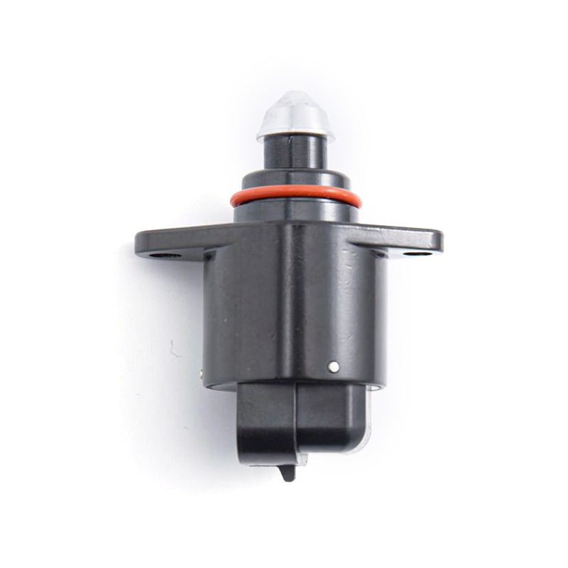
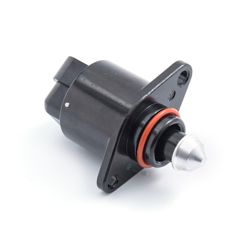
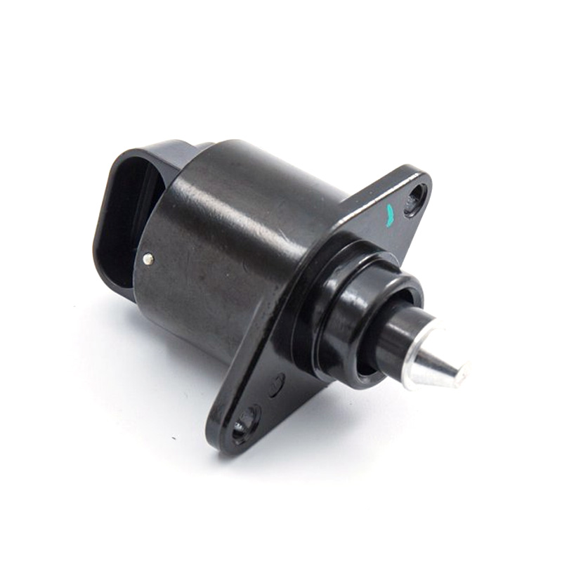
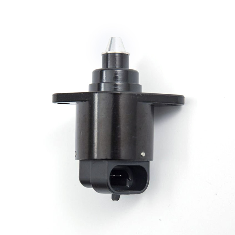
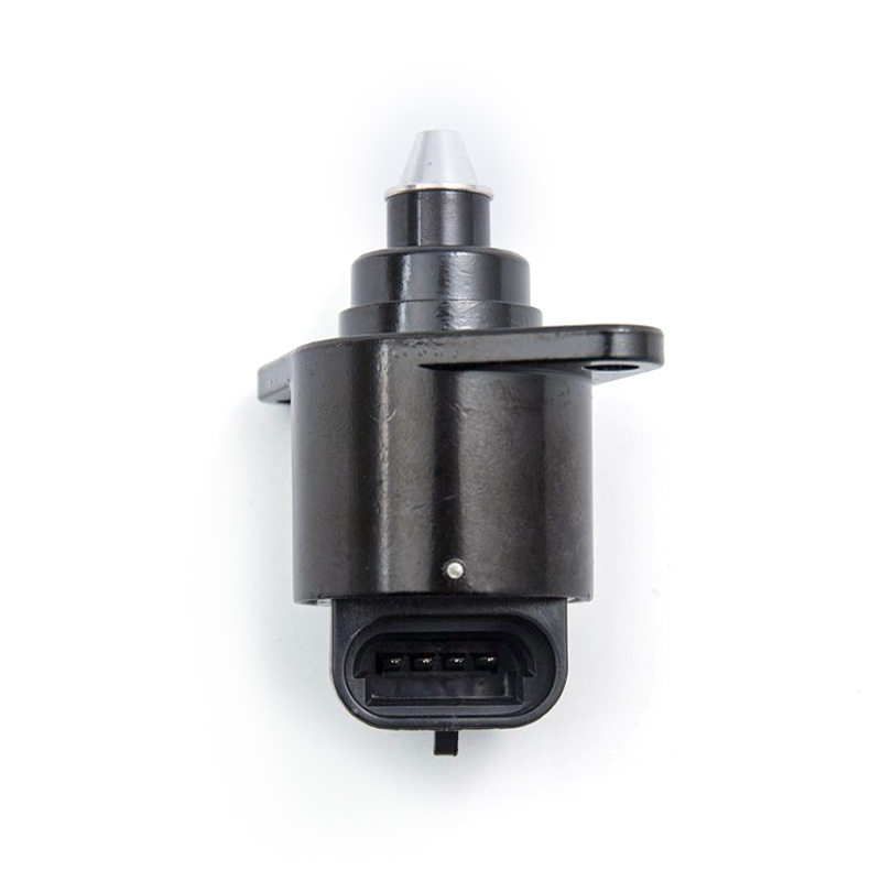
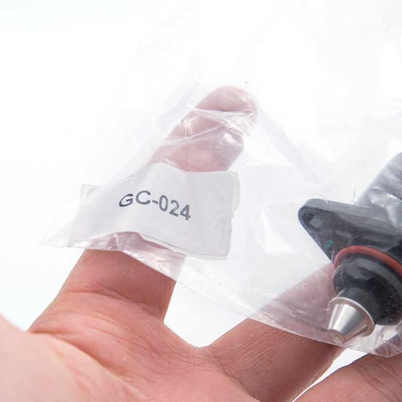
GC-024
REFERENCE OE:
SHORT CODE: C1351
OPEL: 817254 17112027
SIMENCE: A95160
DELPHI:ICD 00127
VDO: AT-59524R
HELLA:6NW009141121;0817254; 93227674
APPLICATION:
OPEL ASTRA F CLASSIC Kombi/Schraqheck;
OPEL COMBO;
OPEL CORSA A Schraqheck/TR;
OPEL CORSA B;
OPEL KADETT E;
OPEL TIGRA
Idle air control valve from China factory for Opel, IACV.
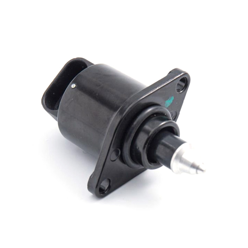
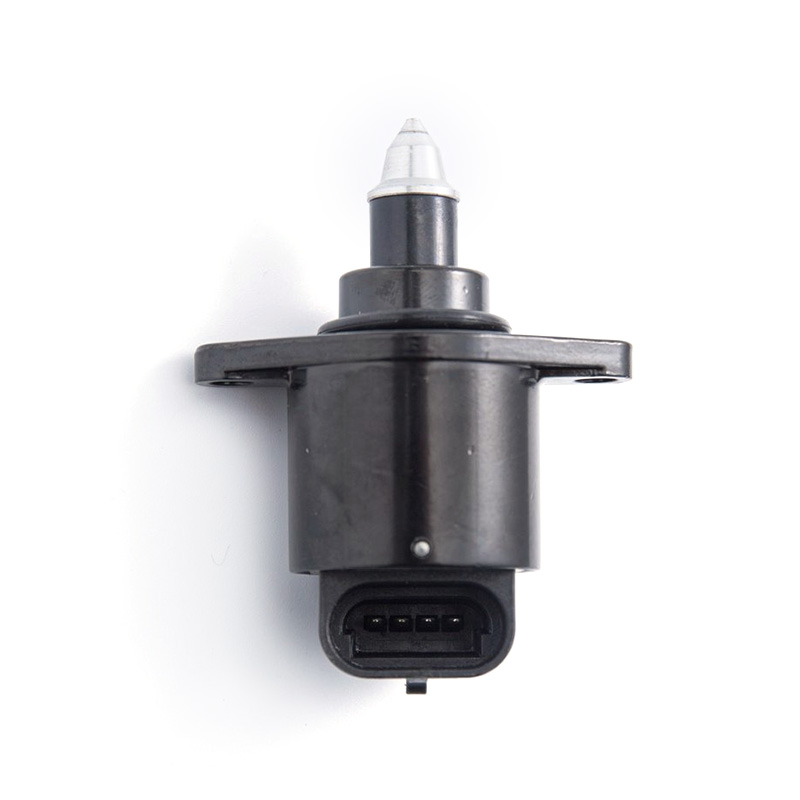
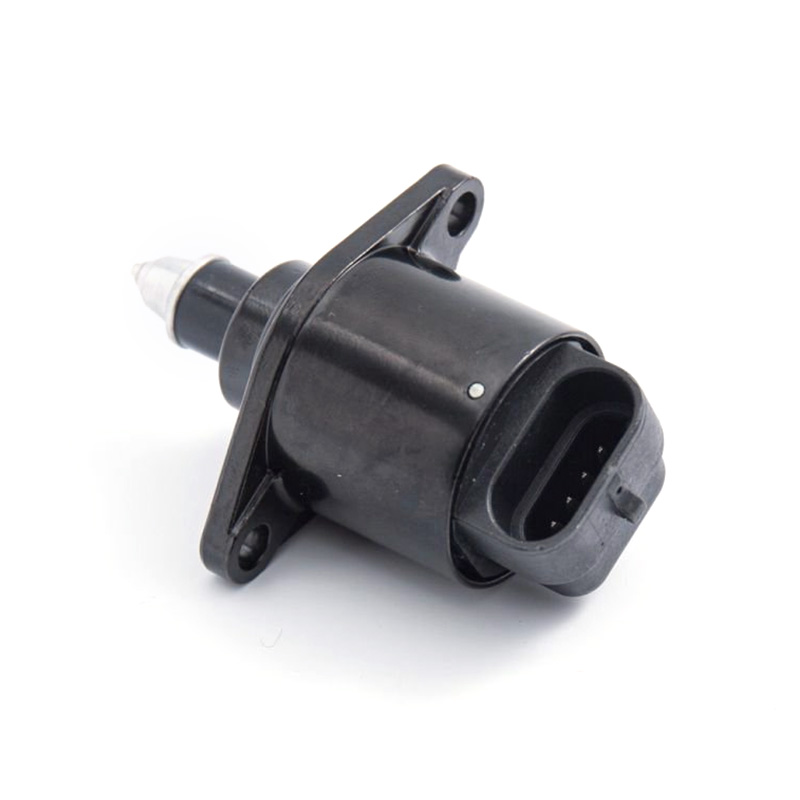
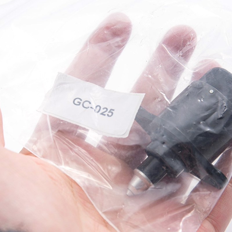
GC-025
REFERENCE OE:
STD: AC495 SHORT CODE:59602
DELPHI: ICD00120
GM: 17059602
VDO: AT-59602R
WELLS: AC167; 93744675; 96434613; 17059602
APPLICATION:
CHEVR AVEO Stufenheck;
DAEWOO KALOS/LANOS/NUBIRA/NUBIRA Stufenheck;
GENTRA 06-07
Idle air control valve from China factory for Chevrolet Aveo Daewoo.
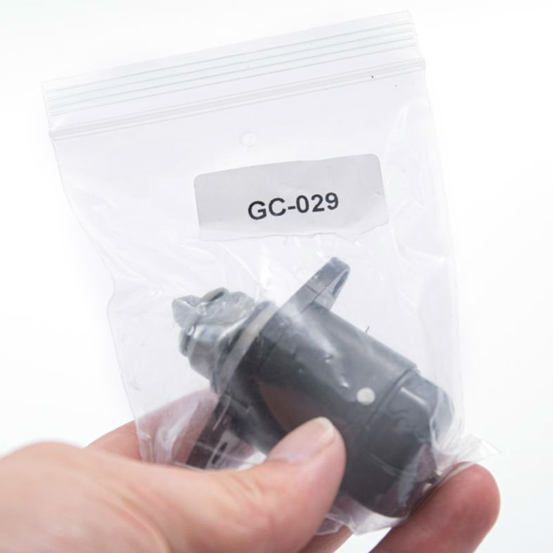
GC-029
REFERENCE OE:
2112-1148300-04
APPLICATION:
LADA
Idle air control valve from China factory for Lada.
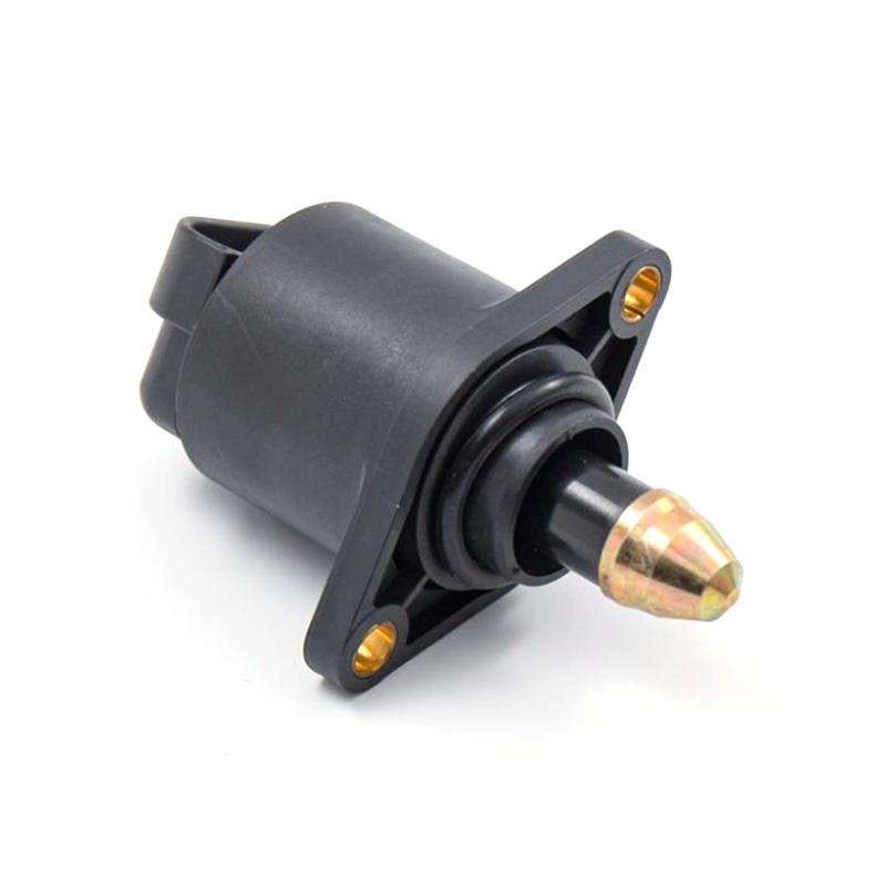
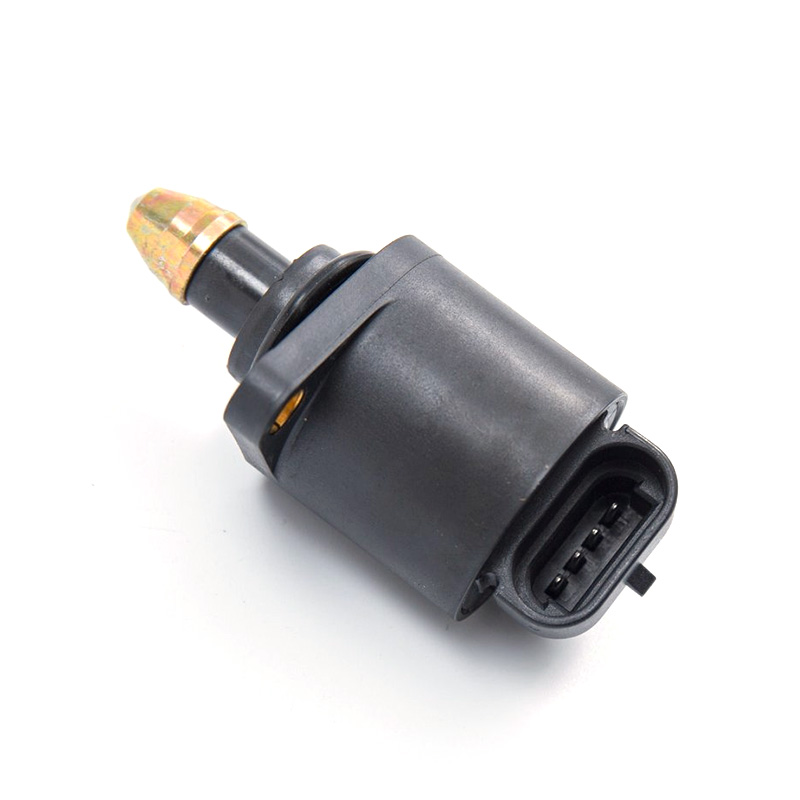
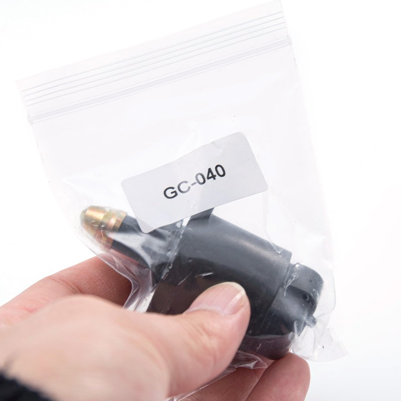
GC-040
REFERENCE OE:
SHORT CODE:B04/01 D5131
MARELLI:230016079057
PEUGEOT:1920N1
SIMENCE:A95269
APPLICATION:
PEUGEOT 205 I Cabriolet(741B,20D)1.6CJ;
PEUGEOT 205 II(20A/C)1.6 Aut;
PEUGEOT 306(7B,N3,N5)1.8/2.0ST;
306 Break(7E,N3,N5)1.8;
PEUGEOT 306 Cabriolet(7B,N3,N5)1.8/2.0ST;
PG 306 Schraqheck(7A,7C,N3,N5)1.8/2.0 Xsi;
PG 309 II(3C,3A)1.6;
PG 405/Break(15B)1.6;
PG405 II(4B)1.6/1.8/2.0/2.0 X4;
PG 406;PG 806;PG BOXER Bus
Idle air control valve from China factory for Peugeot 205 306.
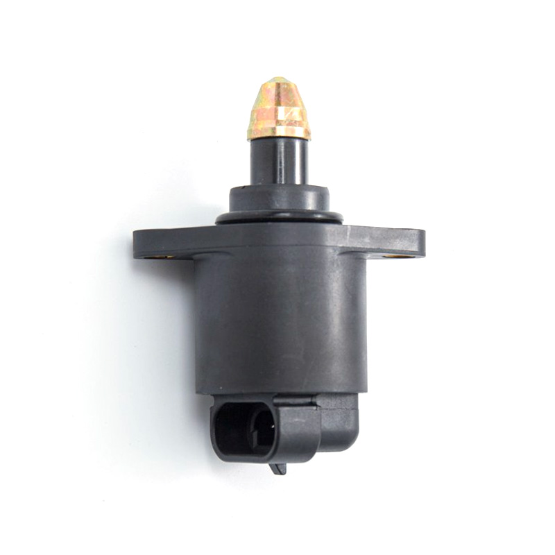
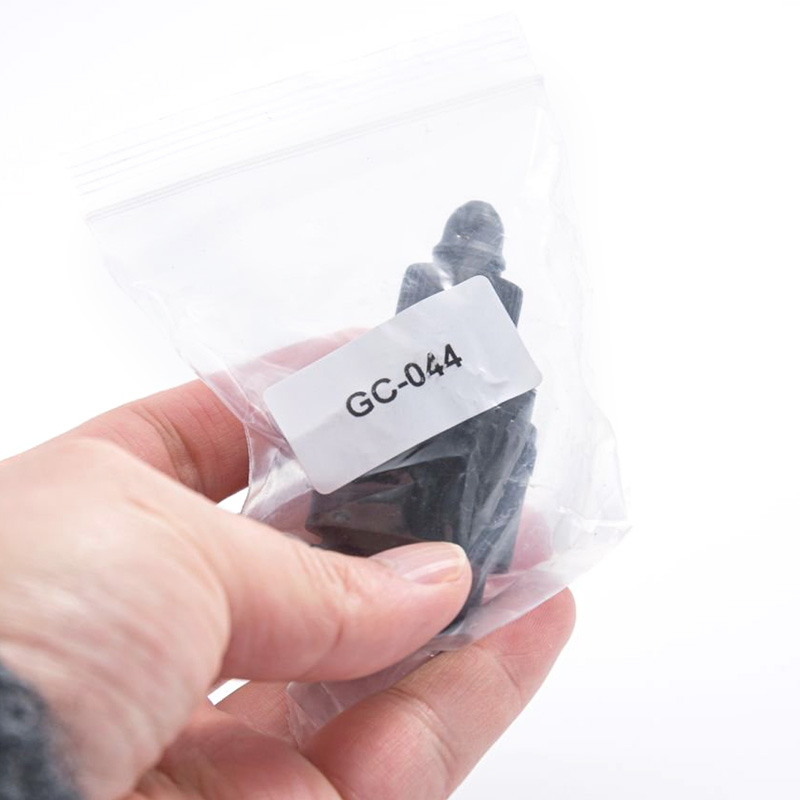
GC-044
REFERENCE OE:
IB01/00
40442902
71718105
APPLICATION:
FIAT 500 1.2;Boblo;Grande Punto;Idea 1.4;Linea 1.4;Palio(178BX)1.2;Panda;Punto;Lanci Musa 1.4;Y(840A)1.2;Ypsilon 1.2 1.4
Idle air control valve from China factory for Fiat Palio.
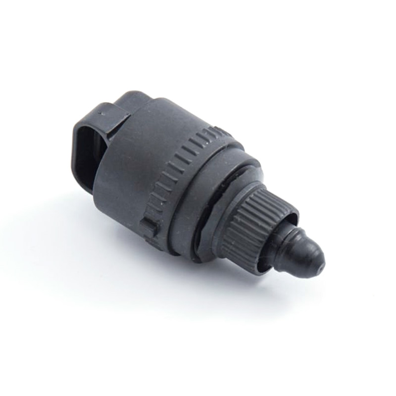
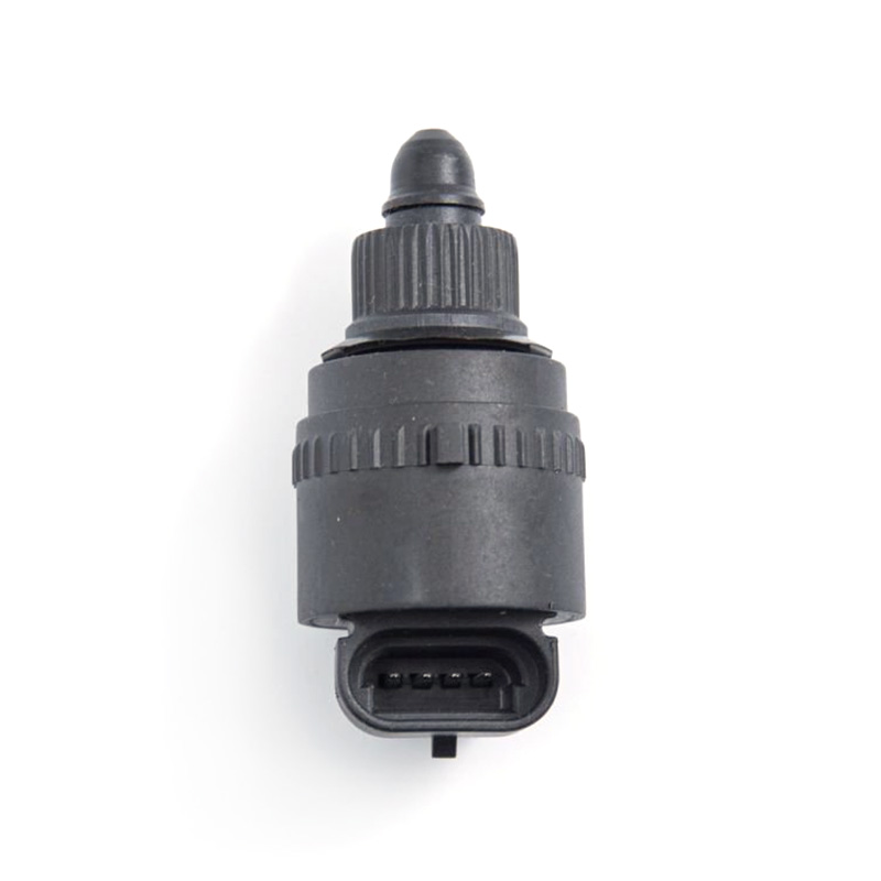
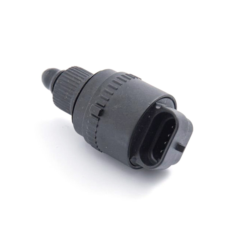
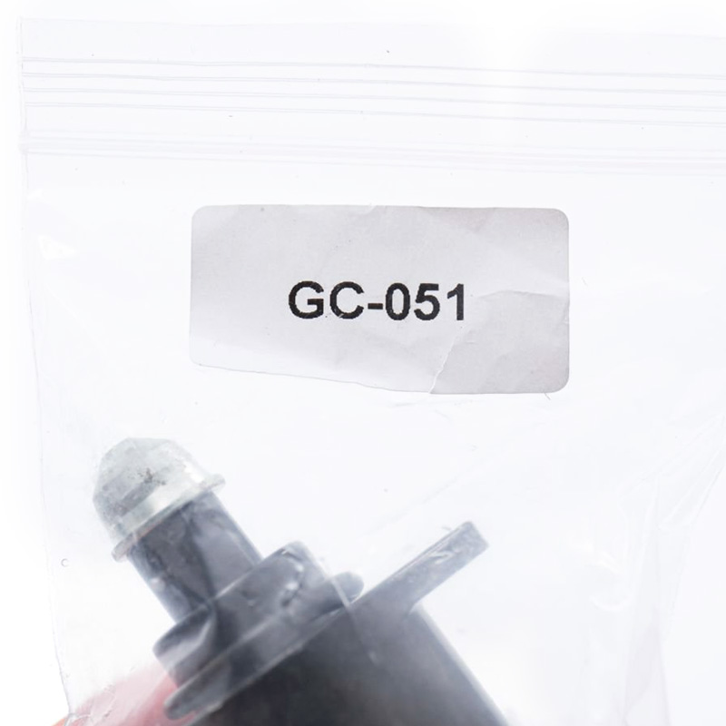
GC-051
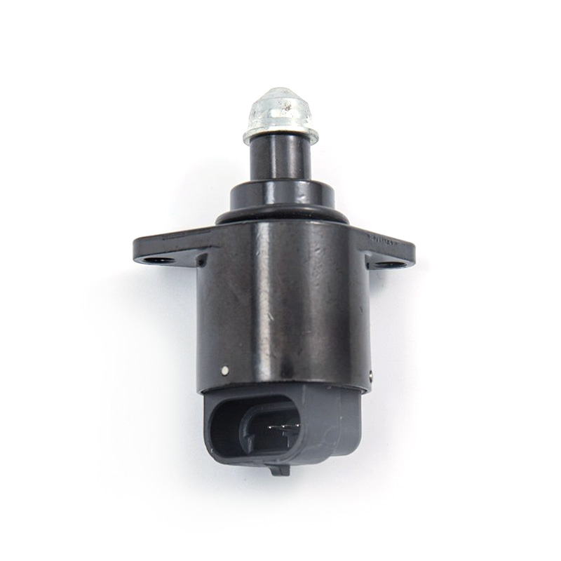
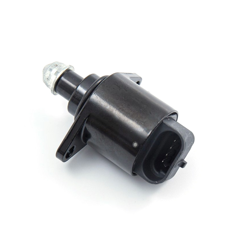
REFERENCE OE:
PEUGEOT:19205F
APPLICATION:
CITRO SAXO(S0,S1)1.4VTS 1.6VTS;PEUGEOT 106 II(1) 1.4i;206 Schraqheck(2A/C)1.4i
Idle air control valve from China factory for Citroen Saxo Peugeot 106 206.
Contact Us
Let's start collaborating

Guocheng is specialized in the R&D and production of key engine components for the automotive and engineering machinery industries.
Product
Stay Connected
(+86) - 577 - 8582 0886 (Tel)
(+86) - 577 - 8582 8085 (Fax)
(+86) - 19730213059 (Phone)
sales@wz-gc.com
No. 205, Baiyu Road, 15th Road, Binhai Park, Wenzhou, Zhejiang, China
Mobile

ODM Engine Management System Components
 English
 русский
 Español
 عربى
عربى Deutsch